


Surface temperature check when spot laser welding plastics
17. 12. 2019
Printed Circuit Boards (PCB) Inspection Using Infrared Camera
17. 12. 2019
Temperature monitoring during laser welding is a very important component, because plastic welding is one of the most common industrial methods used to permanently join parts. There are several plastic welding technologies: hot body, hot gas, friction, ultrasound, and laser welding. Laser welding is ideal for welding very small plastic parts together because of the miniscule size of the laser beam. The beam passes through the transparent plastic and stops on the underlying component. At this point, the joint begins to heat until the two parts are joined together. By placing several laser beams side by side, operators can create any shape and size for the molded contour. However, this process must be monitored to ensure the long-term quality of the weld.
The Problem
A leading automotive company (which will remain unnamed) develops innovative solutions for compression-ignition and combustion engine support systems. Their products require extensive laser welding. Yet in order to produce high-quality components, they need to monitor the entire contour of their welds as they join plastic parts to the DC motor case. If the weld surface does not reach the desired temperature, the weld will not be tight. The company approached us to obtain a solution that would enable them to achieve high homogeneity throughout the weld contour so that they could detect damaged laser beams in the welding head and prevent the production of non-compliant pieces.
The Workswell Solution is temperature monitoring during laser welding
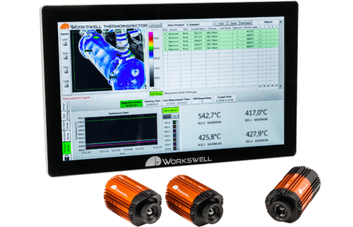
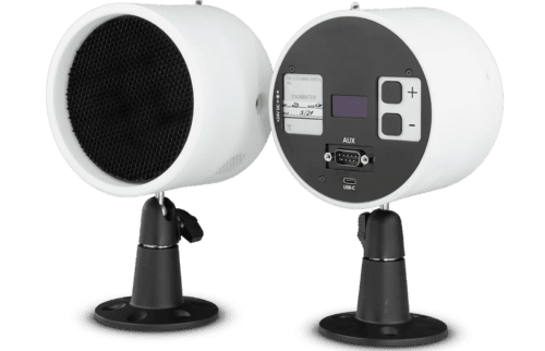
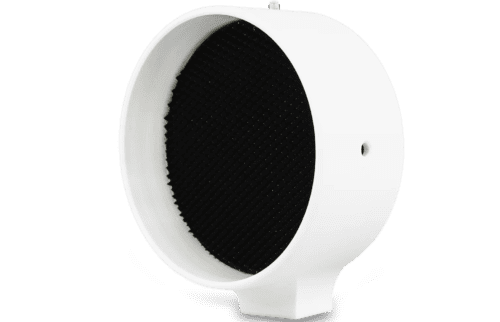
We deployed the ThermoInspector thermal imaging system within our client’s production line. The ThermoInspector is built to monitor production processes, temperature stability and homogeneity, and input – output temperature. Up to 4 WIC thermal imaging cameras can connect simultaneously in ThermoInspector.
Due to the size and shape of the welded parts, we recommended that our client use two WIC thermal imaging cameras and connect them to the ThermoInspector control unit via Ethernet cable. The thermal cameras were placed on static holders facing each other, with each covering one side of the welded piece to monitor the entire contour of the weld. The system was configured to Fixed Time Measurement Mode, which means that the camera monitors the area in the image (ROI) for a fixed number of pictures after the trigger signal. In this case, we fixed the number of pictures at one.
The control PLC brings the trigger signal to the ThermoInspector, and it activates when the welding head starts to weld. Since the welding head obstructs the camera’s view of the weld, the system is set to Start Delay until the welding head is up and the cameras have a direct view of the weld. Postponement of the start of measurement can be used for thermal imaging cameras calibration (NUC), which needs to be performed at least every 10 minutes to ensure the consistency and accuracy of the measured temperatures. If the temperature limit is not met within one of the ROI, an alarm displays on the screen to informs the operator. The system also saves a record to the control computer. Furthermore, digital outputs inform the control PLC of the wrong weld. After each weld, measurement data is sent to the internal database via the TCP/IP protocol. There, it is paired with the data-matrix code of the respective piece to archive the monitoring results.
We chose rectangles along the entire weld contour as the optimal ROI because each rectangle corresponds to one laser beam on the welding head. This makes it easy to identify which beam is damaged. However, the ROI are adjustable throughout the process, and the camera evaluates all measured data in real time. The ThermoInspector monitors maximum measured values/temperatures and compares them against the set limits. The entire process is then visualized for operators on the touch control computer.
