


Surface temperature check when gluing laminate
17. 12. 2019
Surface temperature check when spot laser welding plastics
17. 12. 2019
Surface temperature monitoring during aluminum soldering joins parts together with a molten auxiliary material – the solder – which has a melting point below that of the components that are to be joined. While all soldering follows this basic formula, convention distinguishes between ‘soft’ and ‘hard’ soldering. If the melting point of the solder is less than 450° C, they are called soft, while solders with a melting point of more than 450° C are called hard.
While the principle behind soldering is simple, there are a variety of methods in use today. Typically, the solder is heated with a hot gas or flame. In any case, hard soldering ensures a greater weld strength, and is appropriate for soldering aluminum or copper pipes. Soft soldering is more common for electronics, and because it requires a lower temperature, a natural gas flame with air is sufficient for a sold solder.
Thermal Cameras and Soldering
Our client (who will remain unnamed) is a leader in the automotive industry. They produce automotive air conditioning and related components, and soldering is a regular part of their production process. They came to us because they found that in order to deliver high-quality products, they needed to monitor the temperature course during aluminum torch soldering. By ensuring that the solder reached the desired temperature, they could guarantee a quality joint of two air conditioning distribution pipes. They also needed a way to ascertain the weld temperature after water cooling in order to avoid burning the operator handling the component.
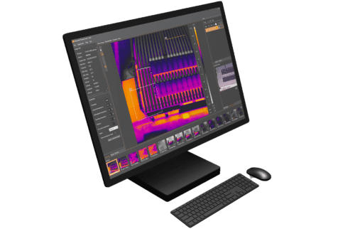
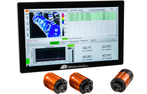
Our Solution: ThermoInspector
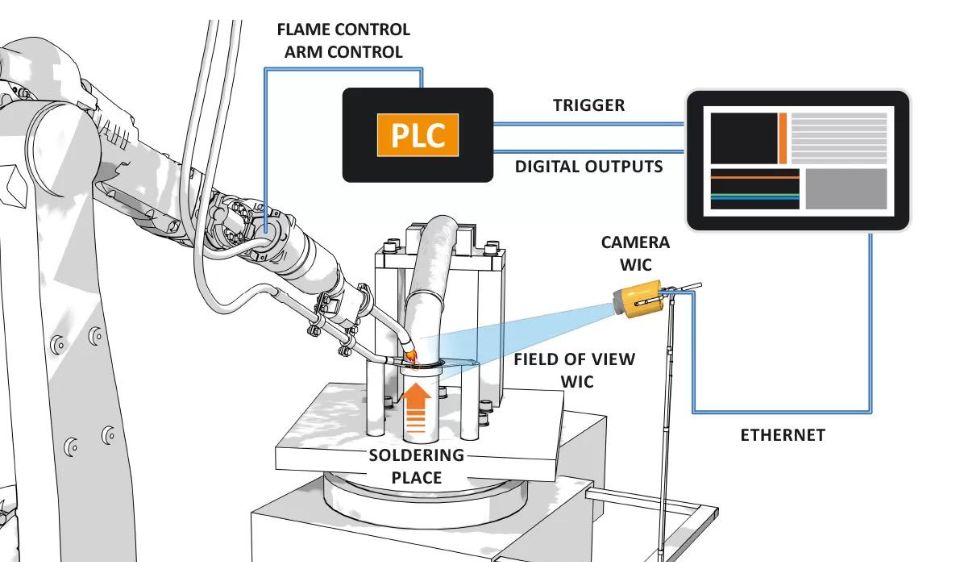
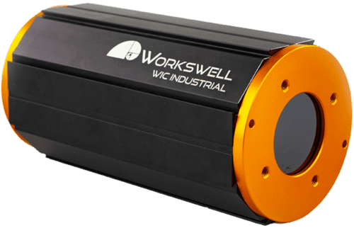
We recommended the ThermoInspector thermal imaging system. ThermoInspector is primarily intended for monitoring production processes, monitoring temperature stability and homogeneity, and input – output temperature monitoring. Up to 4 WIC thermal imaging cameras can connect simultaneously in ThermoInspector.
In this particular case, one thermal imaging camera connected to the ThermoInspector control computer via Ethernet cable was sufficient. The thermal camera was placed on a static holder and adjusted until it was perpendicular to the soldered area, at a sufficient distance from the flame to prevent damage and inaccuracy. Then, the system was configured to Start/Stop Measurement Mode, which means that the camera monitors the respective image area (ROI) during the active incoming trigger signal; the measurement starts on the leading edge and ends on the trailing edge.
The control PLC brings the trigger signal to the ThermoInspector system. It activates when the flame starts to solder, and deactivates when soldering terminates. The second trigger signal comes when the soldered area is cooled with water. Here, even a short signal from the PLC is sufficient. If the temperature limit on any of the ROI is not met, an alarm displays on the screen and informs the operator. ThermoInspector saves a record to the control computer for each solder. The system also has digital outputs that inform the control PLC of the wrong soldering course or high second measurement temperatures.
We chose polygons as the optimal ROI because they form a precise copy of the soldered area. However, ROI can be adjusted throughout the production process, since the unit evaluates data in real time.
In the first round of monitoring, the maximum measured value/temperature is compared against the lower limit of the optimal temperature for soldering. During the second round, the temperature is compared against the upper limit to make sure that operators are not burned when handling the component. The ThermoInspector then displays a visualization of the entire process for operators to inspect.